Process Development Tips and Tricks for Effective Flexible Circuit Laser Processes
Optimizing PCB laser processing for production requires a holistic view of the laser processes and their place in the production line. Taking the time to understand how those factors interact allows you to make informed decisions about where to focus your efforts and helps you to create a production process that effectively supports your organization’s unique set of operational goals. But since process development is iterative and always ongoing, you will need to devote the necessary time to test, document, adjust and improve your process library. Following basic process development principles and best practices with a focus on constant improvement will not only allow you to be more flexible in response to changes in requirements but the resulting production processes will be better aligned to your business goals.
Choices, choices, choices. What defines a good process?
An important point to consider is that the definition of a good process may vary between companies, the product being processed, the phase of a project and/or production backlog, and even from individual to individual.
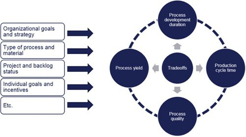
In theory, there are always trade-offs to be made among variables such as process development duration, cycle time, quality and yield. Looking at this question from an organization’s perspective, the process should support the organization’s goals and strategy, each of which have an impact on company priorities. One company may prioritize speed to market over yield and process throughput cost. For this company, a good process might be defined as the first process to meet the minimum product requirements, allowing the company to quickly deliver on their commitments. Another company may prioritize quality and yield over other factors. For this company, a good process might be defined as one which exceeds certain stringent quality and yield requirements, despite higher process cycle times. Yet another company may prioritize process cycle times or other factors.
Which model does your company fit?
The product being processed can also have an impact on how a good process might be defined.
For complex multilayer build-ups where yield loss in the final product can skyrocket, a “good” laser process may require a focus on higher quality than an equivalent double-sided FPC laminate process. Alternatively, the product material might be more expensive on one product than another, in which case yield might be prioritized higher. The phase of a given project or the level of production backlog may similarly impact the priority of quality and yield, productivity, or time to develop such a process.
At a human level, one can even think about how different employee roles and responsibilities impact this question. Depending on organizational incentives, management structures, etc., different individuals may have different personal priorities that can influence their perception of a good process. A process engineer being pushed or incentivized to get the finished product out the door and qualified as quickly as possible may prioritize process development speed over yield or process cycle time. The factory manager, on the other hand, may be watching over total production costs and total production output and, therefore, prioritize these factors differently. Ideally, in a well-run organization, all employees will be aligned to the organization’s goals and strategies and be cognizant of the product, project phase, and product backlog. Often that is not the case and needs to be continuously monitored and worked on.
Why are there tradeoffs in process development?
As discussed above, different circumstances will impact the relative priority of process development duration, process cycle time, process quality, and process yield in defining a good process. The reasons why it’s not possible to deliver equally on these factors may not be clear to everyone.
Process development duration
It takes time to develop processes. In an ideal world, one would have access to a library of canned processes for every possible combination of via size, material, depth, quality, and target drill time. The massive diversity in process requirements and continuous evolution of the market prevents a single such library from being developed. Furthermore, developing processes for more demanding applications, whether due to sensitive materials, unusual feature characteristics, or stringent process quality, yield, or cycle time requirements, often requires significant trial and error to meet all the success criteria. As a result, each manufacturer will need to develop processes that best suit their needs, developing their own process libraries based on their unique set of products, customer requirements, cost profiles, market conditions, goals, and strategies. In building up such libraries and making use of known-good processes, process development duration can be reduced over time.
Process cycle time
Laser processing cycle time can be broken down into a few categories: time spent drilling features (drill time), time spent moving the laser between features (move time), time spent aligning to features (alignment time), time spent placing and removing the material on the system work table (handling time), and any time that the system spends performing additional tasks. Process development will generally affect drill time, sometimes also move time, but generally none of the other factors which are mainly characteristics of the system and handling methods.
Process quality and yield
Process quality specifications differ between flex manufacturers. This can be traced back to both the diversity in company priorities as well as the diversity in downstream processing. Different downstream processing, such as types and effectiveness of patterning, desmear, etch, plating, and other processes, will all impact the laser drilling quality characteristics necessary to achieve a given end-product yield. Similarly, yield requirements, the required percentage of product output meeting quality specifications — can differ between flex manufacturers. While all manufacturers prefer high laser processing and end-product yields, sometimes the cost profiles of yield loss versus process cycle time will favor a faster process over a few percentage points in yield.
Example tradeoffs
In an extreme example of the tradeoff between cycle time, process development duration, and process quality/yield, a process engineer might choose to use a single laser pulse for a large-diameter through-via process. It would be an extremely fast process (cycle time) and have been very quick to develop (process development duration) but be very unlikely to meet any of the process quality or yield requirements for this application.
In an alternative extreme example, favoring process yield and extremely stringent process quality requirements, a process engineer might spend years making adjustments before meeting the necessary quality requirements, running thousands of panels through the entire manufacturing process flow to understand and improve on the end-product yield. In practice, process development activities fall somewhere in between these extreme examples, balancing the relative priorities of each of these key criteria.
Flex laser processing basics: Developing a process
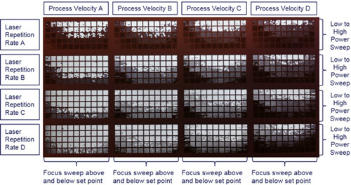
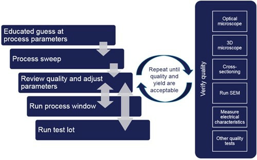
Although you may already have some idea of a flex laser process starting point, each new material and application generally has unique, unforeseen challenges. As a result, it is generally a good idea to generate several test grids on unpatterned materials to perform a broad sweep of the process space around that process starting point. For very new applications where the starting point is less clear, that process sweep can be an extensive design-of- experiments (DoE) around laser power, laser focus, laser pulse repetition frequency (PRF), process velocity, number of process steps, and tooling motions. For more well- understood applications, this process sweep might be limited to varying laser power and focus.
This process sweep would typically be followed by an iterative process of verifying quality, adjusting parameters, running process window tests, test lots, and eventually going into production.
For processes to eventually be used with patterned material and small internal-layer capture pads, the process developed on equivalent unpatterned material would then be revalidated on this patterned material in order to validate accuracy and any process shifts due to the different thermal response of the smaller pads. If that patterned material is scarce, evaluate smaller process shifts using selective processing of individual circuits on the panel.
Process robustness verification
At this point, we can introduce key process development concepts surrounding process robustness. Process robustness can be defined as the process’ ability to meet the process quality specifications across the design tolerances in system characteristics as well as slight changes to system and material characteristics due to environment changes, handling, and contamination over time. Different manufacturers and even different product models each might have different tolerances on collimated beam size, laser spot size, focus accuracy, power control, and work table flatness as a few key examples. Similarly, the system, the material, and the process will be impacted by extrinsic factors such as facility temperature and humidity, facility vacuum, and compressed air pressure and flow rate, etc. that can impact process quality if not managed properly.
In short, process robustness is a key factor in ensuring high yield processes with consistently high quality. The alternative to spending time developing robust processes is accepting lower yields, system downtime and the expense associated with constant system adjustment and cleaning, and the higher expense associated with more stringent environmental control.
Process windows
Process windows are a key method of quantifying the process robustness. Process window tests typically measure how much laser fluence (laser energy per unit area) change the process can tolerate before the process no longer meets quality specifications. Fluence is used as an evaluation metric due to its vital role in material ablation (removal). Furthermore, each of the system tolerances listed above (e.g., spot size, focus accuracy, power control, etc.) have an impact on either the laser energy or area over which that energy is delivered. Some manufacturers measure process window by varying laser focus above and below the process setpoint for the specified application. Some manufacturers measure process window by varying laser energy above and below the process setpoint for the specified application. Others do so by varying both laser focus and laser energy. No matter the precise method, it is critical to validate that the chosen process can withstand real world manufacturing conditions, considering the fluence control accuracy and stability of the system you have purchased.
Laser focus
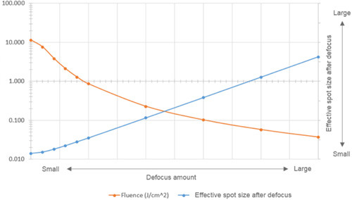
For most laser processes, it is critical to find laser focus accurately. The reason for this is again related to the importance of laser fluence for material ablation. Not only will an out-of-focus laser spot be larger and therefore lower fluence, most lasers also suffer from lower beam circularity and higher beam distortion the further the laser spot is out of focus. This can result in poorer-quality and less predictable processes.
Note that it is equally critical to find and verify laser focus accurately both during process development and during production. If the process was developed in focus, but processed out of focus — or vice versa — the process quality will suffer significantly in production. Note as well that the more accurately and consistently your laser system can find focus , the more consistent your process will be. There are times that it is acceptable and even desirable to process out of focus, such as in clearing dielectric material from a blind via using the top copper opening as a conformal mask. However, even in these circumstances, in order to ensure a consistent process, it is important to have found the focus point accurately before purposely defocusing the beam by a known amount.
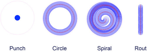
Tooling motion choice
While every laser tool manufacturer may have slightly different options and names for tooling motions, common choices include punches, circles, spirals, and routs. Each tooling motion has unique characteristics that result in different typical uses. Punches may be used when the feature size is approximately equal to the laser spot size and are generally the fastest via formation method when it is possible to use them.
Circles can be used effectively when the via sizes are larger than the laser spot size. Since circle tooling motions only ablate the perimeter of the circle, it is often necessary to follow up with inset circle processes to remove more of the internal material to achieve a robust process. Such multi-circle processes are described in more detail later.
Spiral tooling motions can similarly be used when the via sizes are larger than the laser spot size. Spirals can be used in place of multiple inset circle processes for more process flexibility.
Finally, rout tooling motions are best used for cutting out or ablating any non-circular shapes. Pulse overlap and material removal rate are two important characteristics to consider for routs. Special process development attention should be given to areas with small turn radii, given the tendency for heat to accumulate in those areas.
Depth-limited vs. through processes
There are distinct differences in process development best practices for depth-limited processes such as blind vias and soldermask removal versus processes that cut completely through a material, such as through-vias and excising parts. For depth-limited processes, one needs to be very careful about cutting too deep into the material and damaging the underlying substrate. On the other hand, for through processes, it is possible to develop much more aggressive processes since one does not have to worry about damaging the underlying material. These differences result in greater difficulty to develop optimal depth-limited processes — one needs to weigh cycle time vs. yield/quality tradeoffs between aggressive and more conservative processes.
In general, to ensure the most robust and high-yield process, it is important to completely clear the top copper using an in-focus spot before proceeding to the dielectric clearing step. Another best practice is to develop blind via and multilayer processes one step at a time. Test out and evaluate process parameters for each step of the via formation process.
For example, perhaps you have a three-step blind via process, cutting the top-copper perimeter with a circle tool first, then removing the interior top-copper slug with a second circle tool, and finally cleaning up the polyimide dielectric with a spiral tool. In such a case, develop and evaluate all three steps individually. Verify that the first perimeter cut fully cuts through the top copper without penetrating the bottom copper. Then, after optimizing the first step process, verify that the central copper slug removal is complete. Finally, after optimizing the second step process, verify that the dielectric removal does not leave any residue and does not cause bottom copper damage.
Alignment points and geometry transforms
There are many factors beyond the scope of this article that affect the registration accuracy between via holes and the landing pad. However, a few common-sense best practices can be followed to improve your registration today.
First, use the same alignment points for all processes, such as laser drilling, patterning, and drilling the tooling holes for layup. This results in the least amount of inconsistency.
Second, use the most accurate tool/process to create the alignment points, in many cases, this will be your patterning process or laser drill. While laser drills will often take more time, and have a higher cost per hole than a punch or mechanical drill, the registration accuracy will be higher.
Third, use the same scaling methods and geometry transforms (e.g., parallelogram, trapezoid, etc.) for your drilling and your patterning processes. This again results in the least amount of inconsistency.
Finally, make sure your alignment points are high contrast, highly consistent, and have a well-defined center at the small scale commensurate with the accuracy that you are trying to achieve. Patterned butterfly-type targets best meet these criteria. However, when used appropriately, cross-hair, circle, and donut targets can be used effectively as well.

Post adapted from "Stepping Up To Laser Processing for Flex ebook authored by Patrick Riechel, Director of Product Marketing at MKS Instruments.
About the Author
Patrick Riechel is Director of Product Marketing for Flexible Circuit Micromachining tools at MKS Instuments. He has over ten years of experience in the design and manufacture of electronics, having held positions at Symbol Technologies, Motorola Solutions and MKS. Patrick has an MBA degree and a Master of Science in Systems Engineering from the Massachusetts Institute of Technology (MIT) as well as a Bachelor of Science of Electrical Engineering from Brown University. As the inventor of seven patents and the catalyst for bringing industrial head-worn computing to Motorola, he was the recipient of the Robert Noyce Fellowship at MIT for his contributions to the field of electronics.
 Ultra-High Velocity