How to Calculate and Optimize Total System Cost of Ownership and Cost per Panel
This application note reviews one possible framework of total cost of ownership and cost per panel, including their main components. When reviewing typical UV laser processing systems, upfront costs and maintenance costs make up the largest percentage of cost of ownership, with the majority of maintenance costs related to laser and optics replacement. As such, system and supplier longevity are especially important in order to depreciate these costs over the longest possible period. This longevity includes not just the length of time before the system becomes irreparably broken, but also the supplier’s ability to continue to support the tool as well as the system’s ability to keep up with the market’s evolving needs.
When it comes to laser processing for flex PCB, how do you calculate and optimize total system cost of ownership (TCO) and cost per panel (CPP)? While every company has their own methods of making purchasing decisions and controlling expenses, this chapter will review one possible framework for doing both in the context of UV laser flex processing.
The Basics
Let’s start with some basics. Two fundamental equations may be used to calculate TCO and CPP:
TCO = CF+CR+CY
CPP = TCO / (L×TP×Y×U)
where CF=fixed costs, CR=recurring costs, CY=yield costs, L=production life of system in hours, TP=throughput in panels per hour, Y=product yield, U=system utilization.
Total system cost of ownership takes into consideration all fixed, recurring and yield costs over the course of the system’s life. Cost per panel amortizes that cost of ownership over the total number of good panels processed over the course of the system’s production life. Now that we have established these equations as our framework, let’s dig deeper to understand how UV laser flex processing impacts each of these individual TCO components.
Fixed Costs (CF)
Aside from the obvious system purchase price and its associated depreciation expense, there are a variety of other – although generally lesser – fixed costs to consider. These can include system installation and personnel training costs, costs to qualify the system prior to running production, floor space allocation or overhead allocation costs, as well as costs related to upgrading facilities to meet the system’s site requirements. Of these costs, manufacturers most often neglect to think about the costs associated with upgrading facilities. Those new to flex circuit production will need to consider upgrading their facilities to avoid common and costly issues in production.
ypical areas to watch for in laser system site requirements include electrical, vacuum, compressed air, environmental air, as well as temperature and humidity. Neglecting any of these can result in poor product yield, scrap, or even damage to and downtime on your valuable UV laser system. Poor electrical power quality and sporadic brownouts and blackouts can often result in unexpected system errors, yield issues and, scrap. Vacuum facilities with inadequate pressure and flow can prevent the system’s debris removal from doing its job, which includes clearing the panel of extraneous material and preventing that debris from adhering to and permanently burning onto the system’s sensitive optics. Furthermore, insufficient vacuum can also be the cause of panel movement or non-flat panel material on the system’s vacuum chuck, resulting in yield loss.
Air Flow and Air Quality
Compressed air is often used on UV laser systems to purge the laser and optics areas inside the system, and in some cases to assist the debris removal vacuum in removing debris from the processing area. Given that this air also flows over and around the system’s sensitive laser and optics, not only air pressure and flow are important, but also air quality. While many laser tools will include filters to clean the incoming air, it is possible to negate the benefit of those filters if that air is of especially poor quality. This is equally true of the facility’s environmental air quality. Despite air purging designs that are common in UV laser processing systems, environmental air containing high levels of particles and oils can result in high maintenance costs associated with more frequent optics cleaning and replacement. Finally, flex material processing requires strict control of temperature and humidity ranges and stability. The accuracies that are typically required for flex processing coupled with flex material and high- accuracy laser systems’ sensitivity to both temperature and humidity changes result in a need for much more stringent environmental control than for other types of PCB processing.
Recurring Costs (CR)
UV laser flex processing systems are like any other capital equipment in that they have recurring utilities, personnel and maintenance costs. Of these, maintenance costs and personnel costs should be given special consideration.
Consumables
Laser and optics replacement costs dominate maintenance costs for such UV laser systems. Both must be considered consumables. Typical high-power UV lasers used for flex processing have lifespans ranging from 1-2 years, although those lifespans may be drawn out if the laser is not in 24/7 use or the laser power used for processing is much lower than the system’s work surface laser power specification. Most optics maintain a similar replacement cadence, which may be longer or shorter depending on the compressed air and environmental air quality, the amount of debris generated by the laser process, the frequency of preventive maintenance optics cleaning, among other factors. The system supplier’s highly trained field service engineers generally perform system troubleshooting and major maintenance, while the customer’s maintenance team will perform more frequent and simpler preventive maintenance tasks. Most laser system suppliers will work with their customers to identify the best service plan to meet their customers’ needs, with consideration for factors such as quantity of systems, usage, location, and budget. Full service plans including or excluding lasers, time and material plans, block labor plans, preventive maintenance only plans and other service plans are all typical options. Many suppliers also include a one-year warranty with their system.
Consistency
A range of factors impact laser processing yield. As discussed earlier, ensure that site requirements are met as your first and fundamental step to ensuring acceptable yield. After this, robust processes must be developed for your particular applications that can accommodate for slight variations in materials, as well as in laser power, laser spot size, laser focus, debris removal, etc. Material and system variations exist even in the most well-designed, well-manufactured and well- maintained materials and systems. However, beyond developing robust processes to accommodate variability, try to actively reduce variability in the laser material interaction process. Specifying and achieving lot-to-lot material consistency avoids the need to redevelop laser processes for each new lot. Demanding accurate and responsive laser power control from your laser system will ensure that the process stays consistent over time and over multiple systems. Verifying the laser system’s dynamic positioning accuracy and its ability to compensate for upstream panel warping via scaling, rotation, parallelogram, and trapezoidal transforms also ensures that laser processed features consistently align to other features on the board.
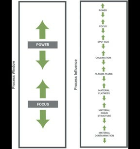
Figure 1. Robust processes actively control for power and focus changes with a robust process window to account for both measurable and immeasurable process influence.
Training
Sufficient training for your laser process engineer and choosing a supplier with a wealth of UV laser process development experience will have a direct positive impact on your bottom line. Trade offs must be made between throughput and yield during process development. Choosing a system with a good production track record in processing your specific applications and materials is one step to ensuring That the system will enable high yield and high productivity on your own production floor. Equally important, however, is choosing a reputable supplier that is experienced with your specific applications and materials and able to offer support to your process development team in order to get the most yield and productivity out of your investment.
Automation
Finally, if you are considering complementing your laser system with an automated material handling solution such as a roll-to-roll handler or stack handler, don’t forget that it also has a critical role to play in ensuring high process yield. Especially as materials become thinner and more easily damaged, your material handling solution should be chosen not just on lowest cost, but also on its ability to handle material without wrinkling, scuffing, or other damage at the maximum throughput available through the laser system you are considering.
Components of Cost Per Panel (CPPC)
Cost per panel amortizes the total cost of ownership over the total number of good panels processed over the course of the system’s production life. That number is calculated by first establishing the total number of panels – good or bad – that could be produced by the tool, multiplying the total tool lifespan by the rate of panel production (throughput). Then multiply that number by the yield rate in order to calculate the total number of good panels that could be processed in that time. Finally, multiply that figure by the system utilization rate in order to determine the number of good panels that would be produced in the time the tool is actually in active production. Having already discussed yield in some detail above, let’s review the three remaining components of CPP – system production life, throughput and system utilization.
System Production Life (L)
While you currently may just be thinking about the demand spike or latest new application that spurred your need for a new tool, this system purchase is an investment that should last you for many years. As a result, keep the factors in mind that are involved in system production life. Obviously, the tool should not fall apart after the first year, un-repairable and useless. Beyond that, however, are some less obvious factors to consider.
The Right Service
Judge how likely it will be that your system supplier will be in business and committed to service your tool throughout the tool’s expected production life. Does the supplier have a history of long system support? Has it been in the UV laser processing business for many years? Can you expect the supplier to continue to support the training of your personnel throughout the system’s life? Beyond your current production application needs, think about the market trends in your business. Verify that the system you plan to purchase will keep up with those evolving market trends. The last thing that you would want is to only get 2-3 years of production life from your investment because it can no longer process the latest materials or applications with sufficient quality or yield. Assuming your company needs to keep up with the latest trends to thinner material and smaller feature sizes, look for systems that have – at the least – excellent power control, fast and accurate beam positioning capabilities for small features and high accuracy.
Throughput (TP)
Similar to yield, laser process throughput is highly impacted not only by system capability, but also by the process parameters that have been developed for the given material and application. On the topic of system capabilities, laser systems will differ in many ways especially with respect to their beam positioning, controls software, and laser technology and those technological differences will each respond differently to each given application and tool path.
On the topic of process parameters, given that each laser system has different benefits and constraints and each material, application, and quality specification will require different processes, each supplier will need to develop new processes for your specific applications. As a result, it is extremely important to compare systems on a mix of several different representative production applications, materials, and tool paths rather than using a simple test grid for throughput and quality comparison purposes. Your supplier’s process development team will typically require the minimum-acceptable quality specifications in order to strike the best balance between throughput and quality. With these real-life applications scenarios, you have the opportunity to test not only the system capability, but also the supplier’s process development team capabilities.
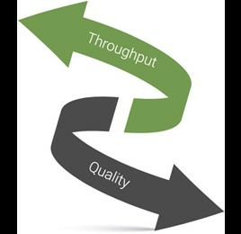
Figure 2. Processes must be developed with an understanding of the process quality and throughput trade offs.
System Utilization (U)
System utilization is the percentage of system time spent in production. It can be calculated via the following formula that subtracts the percentage of time spent on unproductive activities:
U = (1-TU) ⁄ W
Where TU = unproductive time per week (in hours) and W=168 hours (total number of hours per week).
Unproductive time (TU) consists of scheduled and unscheduled downtime, nonscheduled time, standby, and engineering time. Scheduled downtime can typically be estimated by reviewing the system’s preventive maintenance guide as requested from the supplier prior to purchase. Unscheduled downtime, on the other hand, is typically less easy to judge. The supplier’s service team should be able to provide reasonable estimates of service event frequency and how long it takes, on average, to perform major interventions such as replacing a laser. System troubleshooting, on the other hand, is often a tricky business that has uncertainties associated with it.
The major factors related to ensuring minimal downtime include the supplier’s service team location, training and experience level, as well as the availability of a local spare parts hub that stocks the most critical system components in order to avoid long transit and customs clearance delays. In addition, look for good system logging and diagnostics functionality in order to ensure that system errors can be more easily identified and analyzed both by the local service team and – if need be – by the supplier’s remote design engineering team.
Besides system-related issues, facilities can also contribute to unscheduled downtime.
Power outages or brownouts, out-of-tolerance temperature, humidity, vacuum, compressed air, or air quality each can negatively impact the system utilization. Finally, given the fact that it can be difficult to differentiate between a system problem and a process issue when diagnosing yield issues, it is also important that your supplier have an experienced applications engineering team that can help diagnose potential issues with your laser process.
Nonscheduled and standby time will be related to your own business practices, operational efficiency, and level of demand rather than system-specific factors. If running single shifts, non-scheduled time will be significant, while 24/7 operation will minimize that time. Similarly, uncovered lunch breaks, meetings, or unavailability of input material will impact standby time.
Engineering time on laser processing systems is dominated by process development time. Especially when introducing and qualifying new processes to your product mix, process development activities can take days, weeks, or even months. In order to minimize that time, especially if you plan to purchase multiple tools, make sure that the systems are designed and the supplier’s service engineers are trained to ensure that the same process can be used across multiple tools. Furthermore, in order to aid and speed process development, look for a system and associated software that has been designed for easy process development, including easy generation of process window tests to ensure robust, high-yield processes.
Application Engineering
Each manufacturer will have different needs, especially with regard to applications, but also in terms of product mix and volume, personnel costs and plant location. Similarly, each system and system supplier will have different benefits for a given set of applications, product mix and volume, and plant location. As a result, it is imperative to compare system process throughput, quality and consistency using a representative set of real production applications and associated tool paths. Furthermore, given the sophisticated nature of UV laser processing systems, make sure your supplier can support you not only with an experienced and knowledgeable service group, but also with a savvy application engineering team in order to support the inevitable process issues that will crop up over the course of your tool usage. In many situations, it is difficult to tease apart system versus process issues. An experienced supplier can help guide you to the quickest possible return to production.
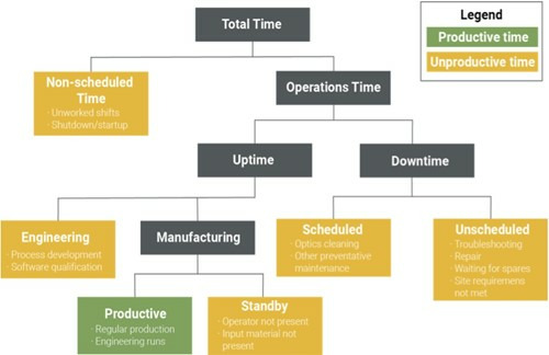
Figure 3. A modified SEMI E10 framework for equipment utilization
Once you have purchased your system, your quest for lowest cost of ownership and cost per panel has not ended. Ensure that your facilities meet the system site requirements in order to avoid future yield issues and excessive system maintenance costs and downtime. Also ensure that your process development team is sufficiently trained to best optimize your processes for both throughput and yield, as well as to avoid the common mistake of sacrificing process robustness for process throughput. Whether you are considering a new UV laser processing system or are attempting to improve the COO and CPP of an existing system, keep this framework and these many factors in mind. A holistic approach that considers system, supplier, personnel, and facility costs, capabilities, and limitations will serve you well and ensure you and your company gets the most out of your investment.
Posts adapted from "Stepping Up To Laser Processing for Flex ebook authored by Patrick Riechel, Director of Product Marketing at MKS Instruments.
About the Author
Patrick Riechel is Director of Product Marketing for Flexible Circuit Micromachining tools at MKS Instuments. He has over ten years of experience in the design and manufacture of electronics, having held positions at Symbol Technologies, Motorola Solutions and MKS. Patrick has an MBA degree and a Master of Science in Systems Engineering from the Massachusetts Institute of Technology (MIT) as well as a Bachelor of Science of Electrical Engineering from Brown University. As the inventor of seven patents and the catalyst for bringing industrial head-worn computing to Motorola, he was the recipient of the Robert Noyce Fellowship at MIT for his contributions to the field of electronics.
 Ultra-High Velocity