Getting Your Facilities Ready for the Introduction of Laser Processing
With so many processes to keep track of in a flex manufacturing line, it can be easy to get lost in the details and begin to rely on your suppliers to address any issues that might crop up. However, given that laser processing equipment and flex materials are both impacted by your facilities, your attention to and investment in clean, stable, and robust facilities and support equipment will quickly pay off in less downtime, higher yield, and — perhaps most importantly — fewer headaches!
It’s fairly common for manufacturers to overlook some of the cost factors associated with upgrading facilities to accommodate the addition of new processing methodologies. For PCB manufacturers considering the addition of laser processing for flex circuit production, there is an entirely new set of considerations to be aware of and to manage effectively if they plan to step into flex PCB laser processing. Getting a handle on those issues early helps to avoid common and costly issues once they’re actually in production.
In this chapter, we’ll consider the factors associated with actually bringing flex laser processing systems on site so you can begin to reap the benefits. Neglecting site preparation can result in poor product yield, scrap, or even damage to — and downtime of — your valuable UV laser system. Furthermore, it is often extremely difficult to isolate process issues from system and site issues once you’re up and running. So, it’s obviously best practice to ensure that your site fully meets requirements before issues such as lower yield or high scrap affect your production efficiency.
Temperature and humidity control
Flex material processing requires an environment with stable temperature and humidity levels. Since the laser system and the flex material itself are highly sensitive to changes in temperature and humidity, a much more stringent environmental control regimen is necessary as compared to other flex PCB processing methodologies.
As flex processing continues to push the envelope of finer lines, smaller vias and smaller pads, the level of drilling accuracy must also increase. Given the high-accuracy requirements associated with flex processing, it’s necessary to minimize the impact of shifts in humidity and temperature — not only in the drilling room but also for downstream processes.
System accuracy and spot quality can be affected by temperature changes due to a variety of reasons, such as alignment issues associated with the thermal expansion and contraction of the system frame, a shift in optics alignment, thermal errors, etc. Certain optics coatings can also be compromised by shifts in humidity. When combined with the impact of those same temperature and humidity shifts on the dimensional stability of your flex material, accurate drilling requires the control of many variables.
Air conditioning vent placement and associated lack of air mixing is often overlooked when considering temperature control. Your thermostat and temperature monitor might be registering minute temperature fluctuations quite some distance from the air conditioning vents. However, if your laser system is placed directly underneath one of those vents without taking measures to baffle and mix that cold or hot air with the ambient air, your laser system could be experiencing much higher temperature fluctuations! Similarly, be aware of any large heat-generating sources and how they are placed and vented relative to your laser tools.
Another commonly overlooked issue is related to the environmental conditions that existed when your system was initially calibrated. If your laser system was installed and calibrated in summer during high factory temperature and humidity levels, you may find that letting the temperature and humidity significantly drop in winter in order to save on utility costs can cause problems. Similarly, if you plan factory shutdowns where you turn off your HVAC or have just moved the system into your facility, make sure to let the system “soak” and stabilize at the set temperature for several hours prior to calibration or processing.
Electrical power
Poor power quality, not to mention power outages and sporadic brownouts, can result in unexpected system errors, yield issues and scrap. While much of this can be controlled through the use of quality voltage regulators, power conditioners and uninterruptable power supplies (where needed), it’s best to start at the source and ensure that clean, conditioned and reliable power is made available to your laser processing systems. While blackouts are perhaps the most obvious contributor to scrap, brownouts and power quality issues can be the most problematic. This is due to the fact that the symptoms of brownouts and power quality issues can look very similar to process and system issues while in fact the root cause is poor input power. Electrical service should be provided by a qualified electrician and should meet local code and regulation.
Vacuum
Flex circuit laser processing systems typically include debris removal vacuum functionality and a vacuum chuck to hold the flexible, malleable and easily-damaged sheets in a stable and flat position. While many equipment manufacturers offer the addition of a standalone vacuum pump, it is often more cost-effective to use the facility’s existing vacuum — especially if considering a multi-system installation. Doing so, however, carries some risks if the implications of multiple systems on a single vacuum line are not considered. When installing your new laser equipment, take time to review your facility vacuum capabilities and plumbing architecture. Before the final step of placing your systems into production, test vacuum pressure and flow rate at each system input when all systems are in operation to verify your facilities under a realistic production scenario.
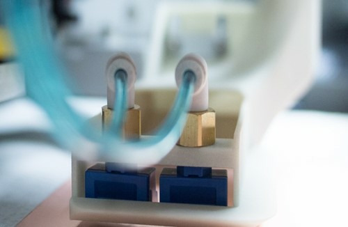
Figure 1. ESI model 5335 debris removal nozzle
During equipment capacity expansions, pump and plumbing that may have previously met system requirements might be insufficient given the addition of new equipment. Also, additional vacuum branching after expansion can cause overall vacuum loss that results in insufficient pressure.
Another common mistake is to test the vacuum pressure and flow when other systems have their debris vacuum off or their chuck vacuum fully covered, both of which do not represent the worst-case production scenario. As a practice, vacuum pressure and flow should be tested again after all equipment is hooked up to the vacuum system and in operation with real panel material — ideally with a production application that exposes the highest number of open vacuum holes on the vacuum chuck.
Vacuum facilities with inadequate pressure and flow can prevent the system’s debris removal from doing its job properly. This can result in damage to the system’s optics over time since the particles ejected during laser processing are not effectively removed, can settle on the nearby optics, and eventually burn onto those optics.
Missing or incompletely-drilled vias can also be caused by poor debris removal due to optics contamination and the debris and processing plasma interfering with the laser reaching the work piece. Finally, insufficient vacuum can also be the cause of panel movement or non-flat panel material on the system’s vacuum work table resulting in a decrease in yield. Each of these issues can result in system downtime due to time spent on extra optics cleaning or root cause investigation. Even worse, more frequent costly optics replacement may be necessary if these site requirements are not satisfied.
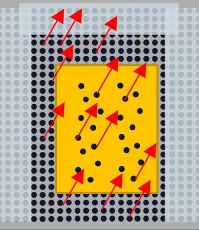
Figure 2. Test with worst-case typical vacuum leakage on all system vacuum chucks with debris removal on for all systems
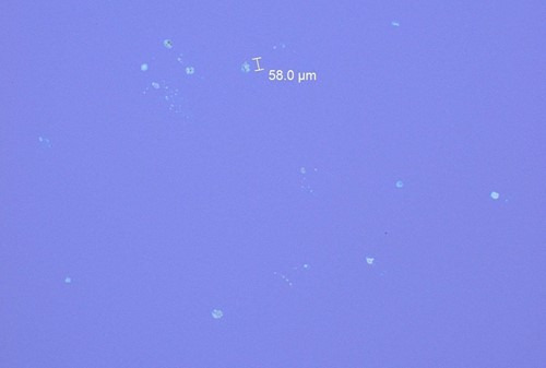
Figure 3. Debris that attaches to optics due to poor air quality or insufficient vacuum. Compressed air an become a major issue if left unchecked
Compressed air is often used on UV laser systems to purge the laser and optics areas inside the system and — in some cases — to assist the debris removal vacuum in removing debris from the processing area. Given that this air also flows over and around the system’s laser and optics, one must take into account not only air pressure and flow but air quality as well. The use of membrane type oil/water separators is essential for ensuring laser-quality compressed air. Standard pneumatics engineering protocols should be followed to allow for proper draining of oil or water from air lines prior to entering the system.
Environmental air quality
The issue of air quality isn’t limited to the quality of compressed air. The facility’s environmental air quality is also a factor. Despite air purging designs that are common in UV laser processing systems, environmental air containing high levels of particles and oils can result in high maintenance costs caused by the need to clean and replace optics more frequently.
Floor vibration
It is also important to minimize floor vibration which can impact system accuracy. Systems can be located anywhere in the manufacturing building from ground floor up to the top floor of a multi-story building. While well-designed systems include vibration-mitigation mechanisms like vibration-absorption foot pads, those are typically designed to only isolate the rest of the factory from vibration from that particular system itself. Obviously, one should avoid placing the laser system near heavy machinery, too close to multiple mechanical drills, or next to other heavy vibration-inducing factory machinery such as the facility vacuum pump, air compressors, or backup generator — especially if you are placing the tool on a higher floor. Typically, the placement of multiple laser systems in the same area does not cause issues, and it is common to find single shop floors containing as many as 40–50 laser systems.
Posts adapted from "Stepping Up To Laser Processing for Flex ebook authored by Patrick Riechel, Director of Product Marketing at MKS Instruments.
About the Author
Patrick Riechel is Director of Product Marketing for Flexible Circuit Micromachining tools at MKS Instuments. He has over ten years of experience in the design and manufacture of electronics, having held positions at Symbol Technologies, Motorola Solutions and MKS. Patrick has an MBA degree and a Master of Science in Systems Engineering from the Massachusetts Institute of Technology (MIT) as well as a Bachelor of Science of Electrical Engineering from Brown University. As the inventor of seven patents and the catalyst for bringing industrial head-worn computing to Motorola, he was the recipient of the Robert Noyce Fellowship at MIT for his contributions to the field of electronics.
 Ultra-High Velocity